
Page 241 - Fluid Power Engineering
P. 241
208 Chapter Te n
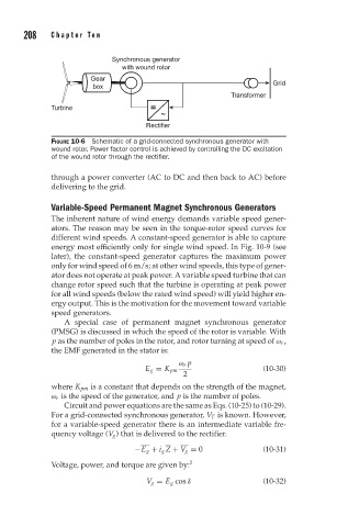
Synchronous generator
with wound rotor
Gear
box Grid
Transformer
Turbine =
~
Rectifier
FIGURE 10-6 Schematic of a grid-connected synchronous generator with
wound rotor. Power factor control is achieved by controlling the DC excitation
of the wound rotor through the rectifier.
through a power converter (AC to DC and then back to AC) before
delivering to the grid.
Variable-Speed Permanent Magnet Synchronous Generators
The inherent nature of wind energy demands variable speed gener-
ators. The reason may be seen in the torque-rotor speed curves for
different wind speeds. A constant-speed generator is able to capture
energy most efficiently only for single wind speed. In Fig. 10-9 (see
later), the constant-speed generator captures the maximum power
only for wind speed of 6 m/s; at other wind speeds, this type of gener-
ator does not operate at peak power. A variable speed turbine that can
change rotor speed such that the turbine is operating at peak power
for all wind speeds (below the rated wind speed) will yield higher en-
ergy output. This is the motivation for the movement toward variable
speed generators.
A special case of permanent magnet synchronous generator
(PMSG) is discussed in which the speed of the rotor is variable. With
p as the number of poles in the rotor, and rotor turning at speed of ω r ,
the EMF generated in the stator is:
ω r p
E g = K pm (10-30)
2
where K pm is a constant that depends on the strength of the magnet,
ω r is the speed of the generator, and p is the number of poles.
Circuit and power equations are the same as Eqs. (10-25) to (10-29).
For a grid-connected synchronous generator, V T is known. However,
for a variable-speed generator there is an intermediate variable fre-
quency voltage (V g ) that is delivered to the rectifier.
−E g + i g Z + V g = 0 (10-31)
Voltage, power, and torque are given by: 2
V g = E g cos δ (10-32)