
Page 243 - Fluid Power Engineering
P. 243
210 Chapter Te n
Inverter Grid
V I
iI
d i I Z 1
Z 1 f V T
V I V T i I
FIGURE 10-8 Schematic of power electronics and control of real and reactive
power with a permanent magnet generator.
at the inverter that regulates how much i DC is drawn by the inverter.
Consider the two cases below:
Lesser i DC is drawn => lesser i g flows through the stator coils
=> Lesser torque is produced to oppose the mechanical torque
from wind => ω the angular speed of rotor increases
Higher i DC is drawn => higher i g flows through the stator
coils => higher torque is produced to oppose the mechanical
torque from wind => ω the angular speed of rotor decreases.
In summary, the PWM inverter is controlled in such a manner that
optimal values of i DC is drawn from the rectifier. This optimal value
determines the optimal value of i g , which determines the optimal
value of torque τ g (Eq. 10-34), which determines the optimum value of
Constant rps turbine Variable rps v=13m/s
turbine
v=12m/s
Power output, kW v=10m/s
v=11m/s
v=9m/s
8m/s
7m/s
6m/s
5
4
Rotor speed, revolutions per second (rps)
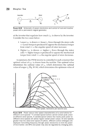
FIGURE 10-9 Power versus rotor speed characteristics of a wind turbine for
3
different wind speeds. A constant-speed turbine cannot extract peak power
at different wind speeds. A variable-speed turbine that tracks peak power at
different wind speeds will deliver higher overall power output. At wind speeds
greater than the rated wind speed of turbine, different control strategies are
deployed: Controlling frequency through power electronics to limit the power
of the inverter; and RPS and power may also be regulated by changing pitch.