
Page 247 - Fluid Power Engineering
P. 247
214 Chapter Te n
Torque
Operating range
Generator Motor
−1 −0.8 −0.6 −0.4 −0.2 0 0.2 0.4 0.6 0.8 1
Slip
Breakdown torque
Increasing R
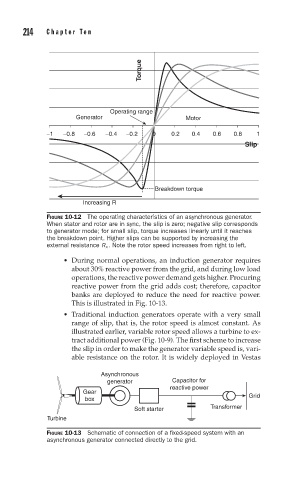
FIGURE 10-12 The operating characteristics of an asynchronous generator.
When stator and rotor are in sync, the slip is zero; negative slip corresponds
to generator mode; for small slip, torque increases linearly until it reaches
the breakdown point. Higher slips can be supported by increasing the
external resistance R x . Note the rotor speed increases from right to left.
During normal operations, an induction generator requires
about 30% reactive power from the grid, and during low load
operations, the reactive power demand gets higher. Procuring
reactive power from the grid adds cost; therefore, capacitor
banks are deployed to reduce the need for reactive power.
This is illustrated in Fig. 10-13.
Traditional induction generators operate with a very small
range of slip, that is, the rotor speed is almost constant. As
illustrated earlier, variable rotor speed allows a turbine to ex-
tract additional power (Fig. 10-9). The first scheme to increase
the slip in order to make the generator variable speed is, vari-
able resistance on the rotor. It is widely deployed in Vestas
Asynchronous
generator Capacitor for
reactive power
Gear
box Grid
Soft starter Transformer
Turbine
FIGURE 10-13 Schematic of connection of a fixed-speed system with an
asynchronous generator connected directly to the grid.