
Page 249 - Fluid Power Engineering
P. 249
216 Chapter Te n
Asynchronous
generator Capacitor for
reactive power
Gear
Grid
box
Soft starter Transformer
Turbine
Variable
resistance
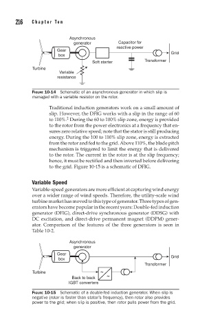
FIGURE 10-14 Schematic of an asynchronous generator in which slip is
managed with a variable resistor on the rotor.
Traditional induction generators work on a small amount of
slip. However, the DFIG works with a slip in the range of 60
2
to 110%. During the 60 to 100% slip zone, energy is provided
to the rotor from the power electronics at a frequency that en-
sures zero relative speed; note that the stator is still producing
energy. During the 100 to 110% slip zone, energy is extracted
from the rotor and fed to the grid. Above 110%, the blade pitch
mechanism is triggered to limit the energy that is delivered
to the rotor. The current in the rotor is at the slip frequency;
hence, it must be rectified and then inverted before delivering
to the grid. Figure 10-15 is a schematic of DFIG.
Variable Speed
Variable-speed generators are more efficient at capturing wind energy
over a wider range of wind speeds. Therefore, the utility-scale wind
turbine market has moved to this type of generator. Three types of gen-
erators have become popular in the recent years: Double-fed induction
generator (DFIG), direct-drive synchronous generator (DDSG) with
DC excitation, and direct-drive permanent magnet (DDPM) gener-
ator. Comparison of the features of the three generators is seen in
Table 10-2.
Asynchronous
generator
Gear
box Grid
Transformer
Turbine ~
Back to back ~
IGBT converters
FIGURE 10-15 Schematic of a double-fed induction generator. When slip is
negative (rotor is faster than stator’s frequency), then rotor also provides
power to the grid; when slip is positive, then rotor pulls power from the grid.