
Page 238 - Fluid Power Engineering
P. 238
Basics of Electricity and Generators 205
ω ω
N N
S
S
δ
V T -E g
V T -E g -E g
-E g V T δ V T
i
i
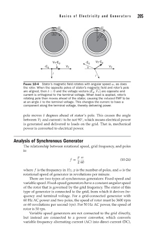
FIGURE 10-4 Stator’s magnetic field rotates with angular speed ω, as does
the rotor. When the opposite poles of stator’s magnetic field and rotor’s pole
are aligned, then δ = 0 and the voltage vectors (E g , V T ) are opposite and
current is orthogonal to the terminal voltage. When load is applied, rotor’s
rotating pole then moves ahead of the stator, causing the induced EMF to be
at an angle δ to the terminal voltage. This changes the current to have a
component along the terminal voltage, thereby delivering power.
pole moves δ degrees ahead of stator’s pole. This causes the angle
between V T and current i to be not 90 , which means electrical power
◦
is generated and delivered to loads on the grid. That is, mechanical
power is converted to electrical power.
Analysis of Synchronous Generator
The relationship between rotational speed, grid frequency, and poles
is:
p ω
f = (10-24)
2 60
where f is the frequency in Hz, p is the number of poles, and ω is the
rotational speed of generator in revolutions per minute.
There are two types of synchronous generators: Fixed speed and
variable speed. Fixed-speed generators have a constant angular speed
of the rotor that is governed by the grid frequency. The stator of this
type of generator is connected to the grid, from which it derives fre-
quency and terminal voltage. For a grid-connected generator with
60 Hz AC power and two poles, the speed of rotor must be 3600 rpm
or 60 revolutions per second (rps). For 50 Hz AC power, the speed of
rotor is 50 rps.
Variable speed generators are not connected to the grid directly,
but instead are connected to a power convertor, which converts
variable frequency alternating current (AC) into direct current (DC),