
Page 296 - Fluid Power Engineering
P. 296
262 Chapter Twelve
a turbine, can cause attenuation or interruption of the signal. The path
of the microwave link forms a volume around the line connecting the
transmitter and receiver, and this volume is called the Fresnel zone.
The first Fresnel zone must be free of obstacles. The width of the first
Fresnel zone can be approximated using: 10
d 1 = λ(1,000d t )(1 − d t /d AB ) = 17.3 d t (1 − d t /d AB )/f
where λ is the wavelength in meters, f is the frequency in GHz, λ =
0.3/f , d t is the distance between the turbine and the closest tower
in km, and d AB is the distance between towers A and B in km. As
an example, consider a 6 GHz microwave signal being transmitted
between two towers that are 25 km apart; the Fresnel zone will be
the widest at the middle. The diameter of the Fresnel zone in the
middle is:
√
d 1 = (300/6,000)12,500(1 − 0.5) = 312.5 = 17 m
In addition to d 1 , the height of the microwave path must be compared
with the height of the obstacle. The height of the microwave anten-
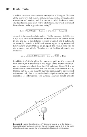
nas on towers is available from the FCC database. Figure 12-2 is an
illustration of the microwave analysis. In case, w is less than 100 m,
that is a turbine is less than 100 m away from an active or proposed
microwave link, then a more detailed analysis must be performed
regardless of interference. The detailed analysis should include
B
d t
w
A
FIGURE 12-2 A and B are locations of microwave towers; w is the distance
from turbine to the closest point on the path between A and B. d t is the width
of the Fresnel zone around the microwave link. Diagram is not to scale.