
Page 35 - Fluid Power Engineering
P. 35
Basics of W ind Energy and Power 13
Wind
Turbine
y
x
A 0 A r A 2
Control Volume
ν 0
ν r
ν 2
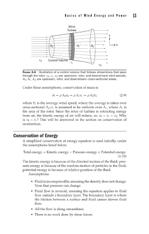
FIGURE 2-4 Illustration of a control volume that follows streamlines that pass
through the rotor. v 0 ,v r ,v 2 are upstream, rotor, and downstream wind speeds.
A 0 , A r , A 2 are upstream, rotor, and downstream cross-sectional areas.
Under these assumptions, conservation of mass is:
˙ m = ρ A 0 v 0 = ρ A r v r = ρ A 2 v 2 (2-9)
where v 2 is the average wind speed, where the average is taken over
cross-sectional A 2 ; v r is assumed to be uniform over A r , where A r is
the area of the rotor. Since the rotor of turbine is extracting energy
from air, the kinetic energy of air will reduce, so, v 0 > v r > v 2 . Why
is v 0 > v r ? This will be answered in the section on conservation of
momentum.
Conservation of Energy
A simplified conservation of energy equation is used initially, under
the assumptions listed below.
Total energy = Kinetic energy + Pressure energy + Potential energy
(2-10)
The kinetic energy is because of the directed motion of the fluid; pres-
sure energy is because of the random motion of particles in the fluid;
potential energy is because of relative position of the fluid.
Assumptions:
Fluid is incompressible, meaning the density does not change.
Note that pressure can change.
Fluid flow is inviscid, meaning the equation applies to fluid
flow outside a boundary layer. The boundary layer is where
the friction between a surface and fluid causes slower fluid
flow.
All the flow is along streamlines.
There is no work done by shear forces.