
Page 37 - Fluid Power Engineering
P. 37
Basics of W ind Energy and Power 15
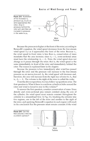
FIGURE 2-5 Illustration
of the increase in p r 0
0
pressure (p 0 to p )as
r
wind approaches the
A 0 A r A 2
rotor; drop in
pressure behind the p 0 p 0
2
rotor (p ) and then an ν 0 ν 2
r
increase in pressure p r 2
in the wake to p 0 .
ν r
Wind
Turbine
Because the pressure is higher at the front of the rotor, according to
Bernoulli’s equation, the wind speed decreases from the free-stream
wind speed (v 0 ) as it approaches the front of the rotor. Because v r ,
the wind speed in front rotor, is less than v 0 , conservation of mass
mandates that the area increase; since v 0 > v r , cross-sectional areas
must have the relationship A 0 < A r . Note, the wind speed does not
change as it passes through the rotor; that is, the wind speed is the
same immediately in front of the rotor and immediately behind the
rotor. The reason is explained later in the chapter.
Because the pressure is low immediately after wind has passed
through the rotor and the pressure will increase to the free-stream
pressure as air moves toward A 2 , the wind speed will decrease and,
therefore, the area will increase from the right face of rotor to A 2 , that
is, A 2 > A r . The volume to the right of the rotor is called the wake.
From the above exposition, two key follow-up questions arise. The
first question is: What if there is a uniform cylindrical tube around the
rotor and wind is forced to stay in this volume? 1
To answer the first question, consider conservation of mass. Since
density and cross-sectional area remain constant along the axis of
the cylinder, the wind speed must remain constant throughout the
cylinder in a streamlined flow. In Fig. 2-6, breaking the cylinder into
two regions, one to the left of the rotor and another to the right of
the rotor, and applying Bernoulli’s equation to each region will result
in the conclusion that the pressure must remain constant. If the wind
FIGURE 2-6 Can the
flow around a rotor be
a uniform cylinder?
A 0
ν 0 Wind ν 2
Turbine