
Page 83 - Fluid Power Engineering
P. 83
Aerodynamics of W ind T urbine Blades 61
Flat plates
Barrier
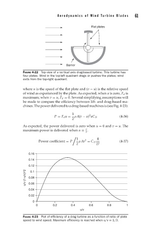
FIGURE 4-22 Top view of a vertical axis drag-based turbine. This turbine has
four plates. Wind in the top-left quadrant drags or pushes the plates; wind
exits from the top-right quadrant.
where u is the speed of the flat plate and (v − u) is the relative speed
of wind as experienced by the plate. As expected, when u is zero, F d is
maximum; when v = u, F d = 0. Several simplifying assumptions will
be made to compare the efficiency between lift- and drag-based ma-
chines.Thepowerdeliveredtoadrag-basedmachinesis(seeFig.4-23):
1 2
P = F d u = ρ A(v − u) uC D (4-36)
2
As expected, the power delivered is zero when u = 0 and v = u. The
v
maximum power is delivered when u = .
3
1 3 4
Power coefficient = P ρ Av = C D (4-37)
2 27
0.16
0.14
0.12
u/v (1-u/v)^2 0.08
0.1
0.06
0.04
0.02
0
0 0.2 0.4 0.6 0.8 1
u/v
FIGURE 4-23 Plot of efficiency of a drag turbine as a function of ratio of plate
speed to wind speed. Maximum efficiency is reached when u/v = 1/3.