
Page 82 - Fluid Power Engineering
P. 82
60 Chapter Four
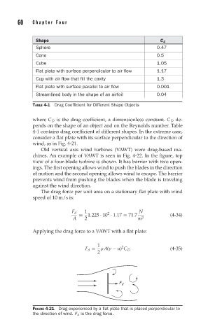
Shape C D
Sphere 0.47
Cone 0.5
Cube 1.05
Flat plate with surface perpendicular to air flow 1.17
Cup with air flow that fill the cavity 1.3
Flat plate with surface parallel to air flow 0.001
Streamlined body in the shape of an airfoil 0.04
TABLE 4-1 Drag Coefficient for Different Shape Objects
where C D is the drag coefficient, a dimensionless constant. C D de-
pends on the shape of an object and on the Reynolds number. Table
4-1 contains drag coefficient of different shapes. In the extreme case,
consider a flat plate with its surface perpendicular to the direction of
wind, as in Fig. 4-21.
Old vertical axis wind turbines (VAWT) were drag-based ma-
chines. An example of VAWT is seen in Fig. 4-22. In the figure, top
view of a four-blade turbine is shown. It has barrier with two open-
ings. The first opening allows wind to push the blades in the direction
of motion and the second opening allows wind to escape. The barrier
prevents wind from pushing the blades when the blade is traveling
against the wind direction.
The drag force per unit area on a stationary flat plate with wind
speed of 10 m/s is:
1 N
F d 2
= 1.225 · 10 · 1.17 = 71.7 (4-34)
A 2 m 2
Applying the drag force to a VAWT with a flat plate:
1 2
F d = ρ A(v − u) C D (4-35)
2
F d
FIGURE 4-21 Drag experienced by a flat plate that is placed perpendicular to
the direction of wind. F d is the drag force.