
Page 86 - Fluid Power Engineering
P. 86
64 Chapter Five
y
y
x
z x D
r
ω β L cosβ+D sinβ
α α
φ φ L
V res v t = ωr(1+b)
γ β γ β L sinβ+D cosβ
v 1 = v 0 (1–a)
(a) (b) (c)
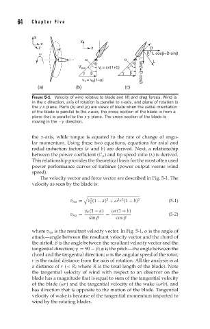
FIGURE 5-1 Velocity of wind relative to blade and lift and drag forces. Wind is
in the x direction, axis of rotation is parallel to x-axis, and plane of rotation is
the y-x plane. Parts (b) and (c) are views of blade when the radial orientation
of the blade is parallel to the z-axis; the cross section of the blade is from a
plane that is parallel to the x-y plane. The cross section of the blade is
moving in the −y direction.
the x-axis, while torque is equated to the rate of change of angu-
lar momentum. Using these two equations, equations for axial and
radial induction factors (a and b) are derived. Next, a relationship
between the power coefficient (C p ) and tip speed ratio (λ) is derived.
This relationship provides the theoretical basis for the most often used
power performance curves of turbines (power output versus wind
speed).
The velocity vector and force vector are described in Fig. 5-1. The
velocity as seen by the blade is:
2
2 2
2
v res = v (1 − a) + ω r (1 + b) 2 (5-1)
0
v 0 (1 − a) ωr(1 + b)
v res = = (5-2)
sin β cos β
where v res is the resultant velocity vector. In Fig. 5-1, α is the angle of
attack—angle between the resultant velocity vector and the chord of
the airfoil; β is the angle between the resultant velocity vector and the
tangential direction; γ = 90 − β; φ is the pitch—the angle between the
chord and the tangential direction; ω is the angular speed of the rotor;
r is the radial distance from the axis of rotation. All the analysis is at
a distance of r (< R; where R is the total length of the blade). Note
the tangential velocity of wind with respect to an observer on the
blade has a magnitude that is equal to sum of the tangential velocity
of the blade (ωr) and the tangential velocity of the wake (ωrb), and
has direction that is opposite to the motion of the blade. Tangential
velocity of wake is because of the tangential momentum imparted to
wind by the rotating blades.