
Page 90 - Fluid Power Engineering
P. 90
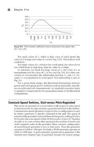
68   Chapter Five


                       0.6
                       0.5
                       0.4
                     C p  0.3
                       0.2
                       0.1
                        0
                             0.05  0.067  0.84  0.1  0.15  0.2  0.25  0.3  0.35  0.4  0.45  0.5
                                            1/λ

              FIGURE 5-4 Plot of power coefficient versus reciprocal of tip speed ratio
              (1/λ =v 0 /ωR).


                 For small values of λ, which is high value of wind speed, the
              value of β is large and value of a is low (Eq. 5-15). This leads to stall
              conditions.
                 For larger values of λ, which is low wind speed, the value of β is
              low, which leads to high drag. Note the value of a is high.
                 In summary, for small and large values of λ, the value of a is
              nonoptimum and the value of C p is low (see Fig. 5-4). It is often con-
              venient to conceptualize the relationship between C p and 1/λ, be-
              cause 1/λ is proportional to wind speed. This relationship is seen in
              Fig. 5-4.
                 For a given blade design, the theoretical relationships between
              power and wind speed, power coefficient and tip speed ratio, and oth-
              ers are calibrated with measurements. An empirical correction factor
              is applied to compensate for the assumptions made in the theoretical
              computations.


        Constant-Speed Turbines, Stall-versus Pitch-Regulated
              The nature of operation of a wind turbine with respect to rotor speed
              is determined by the type of electric generator attached to the turbine.
              Constant rotor speed operation is typical when a configuration is used
              in which a generator is directly connected to the grid. The speed of
              rotation of the generator is derived from the frequency of the grid. On a
              50-Hz grid, the rotor speed will be 50 60/(number of poles/2). Number
                                            ∗
              of poles is an even number that represents the number of north and
              south magnetic poles in the generator. Most common configuration
              of asynchronous generator is two or four poles. Thus, the generator
              operates at 3,000 or 1,500 rpm. Similarly, a 60-Hz generator operates at
              3,600 or 1,800 rpm. A grid-connected asynchronous generator is the
              simplest and cheapest type of generator because the output energy