
Page 89 - Fluid Power Engineering
P. 89
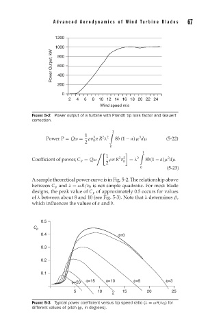
Advanced Aerodynamics of W ind T urbine Blades      67


                       1200
                     Power Output, kW 1000

                        800
                        600
                        400
                        200

                         0
                            2  4  6  8  10 12 14 16 18 20 22 24
                                        Wind speed m/s

              FIGURE 5-2 Power output of a turbine with Prandtl tip loss factor and Glauert
              correction.

                                  1   3  2 2  1        3
                   Power P = Qω =  ρv π R λ   8b (1 − a) μ dμ     (5-22)
                                     0
                                  2
                                            0
                                           1
                                                         1
                                                2 3
                                                                   3
              Coefficient of power, C p = Qω  ρπ R v 0  = λ 2  8b(1 − a)μ dμ
                                           2
                                                        0         (5-23)
              A sample theoretical power curve is in Fig. 5-2. The relationship above
              between C p and λ = ωR/v 0 is not simple quadratic. For most blade
              designs, the peak value of C p of approximately 0.5 occurs for values
              of λ between about 8 and 10 (see Fig. 5-3). Note that λ determines β,
              which influences the values of a and b.


                 0.5
              C p
                 0.4                           φ=0

                 0.3

                 0.2

                 0.1
                             φ=20  φ=15   φ=10       φ=5          φ=3

                              5        10    λ   15        20       25
              FIGURE 5-3 Typical power coefficient versus tip speed ratio (λ = ωR/v 0 ) for
              different values of pitch (φ, in degrees).