
Page 91 - Fluid Power Engineering
P. 91
Advanced Aerodynamics of W ind T urbine Blades 69
Constant rps turbine v=12m/s Variable rps turbine
v=13m/s
Power output, kW v=10m/s
v=11m/s
v=9m/s
8m/s
7m/s
6m/s
5
4
Rotor speed, revolutions per second (rps)
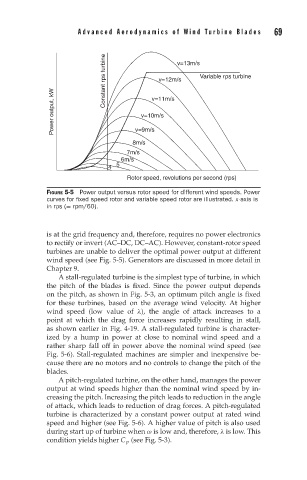
FIGURE 5-5 Power output versus rotor speed for different wind speeds. Power
curves for fixed speed rotor and variable speed rotor are illustrated. x-axis is
in rps (= rpm/60).
is at the grid frequency and, therefore, requires no power electronics
to rectify or invert (AC–DC, DC–AC). However, constant-rotor speed
turbines are unable to deliver the optimal power output at different
wind speed (see Fig. 5-5). Generators are discussed in more detail in
Chapter 9.
A stall-regulated turbine is the simplest type of turbine, in which
the pitch of the blades is fixed. Since the power output depends
on the pitch, as shown in Fig. 5-3, an optimum pitch angle is fixed
for these turbines, based on the average wind velocity. At higher
wind speed (low value of λ), the angle of attack increases to a
point at which the drag force increases rapidly resulting in stall,
as shown earlier in Fig. 4-19. A stall-regulated turbine is character-
ized by a hump in power at close to nominal wind speed and a
rather sharp fall off in power above the nominal wind speed (see
Fig. 5-6). Stall-regulated machines are simpler and inexpensive be-
cause there are no motors and no controls to change the pitch of the
blades.
A pitch-regulated turbine, on the other hand, manages the power
output at wind speeds higher than the nominal wind speed by in-
creasing the pitch. Increasing the pitch leads to reduction in the angle
of attack, which leads to reduction of drag forces. A pitch-regulated
turbine is characterized by a constant power output at rated wind
speed and higher (see Fig. 5-6). A higher value of pitch is also used
during start up of turbine when ω is low and, therefore, λ is low. This
condition yields higher C p (see Fig. 5-3).