
Page 77 - Fluid Power Engineering
P. 77
Aerodynamics of W ind T urbine Blades 55
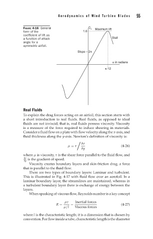
FIGURE 4-16 General C L Maximum lift
form of the 1.6
coefficient of lift as
a function of attack Stall
angle for a
symmetric airfoil.
Slope = 2π
α in radians
π/12
Real Fluids
To explain the drag forces acting on an airfoil, this section starts with
a short introduction to real fluids. Real fluids, as opposed to ideal
fluids are not inviscid, that is, real fluids possess viscosity. Viscosity
is a measure of the force required to induce shearing in materials.
Considerafluidflowonaplatewithflowvelocityalongthe x-axis,and
fluid thickness along the y-axis. Newton’s definition of viscosity is:
∂v
μ = τ (4-26)
∂y
where μ is viscosity, τ is the shear force parallel to the fluid flow, and
∂v
∂y is the gradient of speed.
Viscosity creates boundary layers and skin-friction drag, a force
that is parallel to the fluid flow.
There are two types of boundary layers: Laminar and turbulent.
This is illustrated in Fig. 4-17 with fluid flow over an aerofoil. In a
laminar boundary layer, the streamlines are maintained, whereas in
a turbulent boundary layer there is exchange of energy between the
layers.
When speaking of viscous flow, Reynolds number is a key concept
ρv Inertial forces
R = = (4-27)
μ/l Viscous forces
where l is the characteristic length; it is a dimension that is chosen by
convention. For flow inside a tube, characteristic length is the diameter