
Page 75 - Fluid Power Engineering
P. 75
Aerodynamics of W ind T urbine Blades 53
+ =
FIGURE 4-13 Illustration of how flow over an airfoil is considered as
consisting of two components, inviscid flow plus circulation.
trailing edge creates a circulation similar to a spinning cylinder. The
reasoning is as follows:
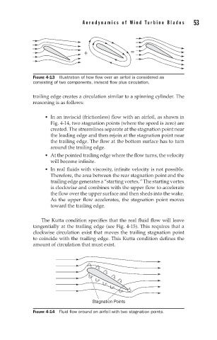
In an inviscid (frictionless) flow with an airfoil, as shown in
Fig. 4-14, two stagnation points (where the speed is zero) are
created. The streamlines separate at the stagnation point near
the leading edge and then rejoin at the stagnation point near
the trailing edge. The flow at the bottom surface has to turn
around the trailing edge.
At the pointed trailing edge where the flow turns, the velocity
will become infinite.
In real fluids with viscosity, infinite velocity is not possible.
Therefore, the area between the rear stagnation point and the
trailing edge generates a “starting vortex.” The starting vortex
is clockwise and combines with the upper flow to accelerate
the flow over the upper surface and then sheds into the wake.
As the upper flow accelerates, the stagnation point moves
toward the trailing edge.
The Kutta condition specifies that the real fluid flow will leave
tangentially at the trailing edge (see Fig. 4-15). This requires that a
clockwise circulation exist that moves the trailing stagnation point
to coincide with the trailing edge. This Kutta condition defines the
amount of circulation that must exist.
Stagnation Points
FIGURE 4-14 Fluid flow around an airfoil with two stagnation points.