
Page 70 - Fluid Power Engineering
P. 70
48 Chapter Four
y
x Pressure= p 0 r Pressure= p 2 r
dr
W
r
ν 1
2bWr
ν 1
bWr
ν 1
ν 1
Wr
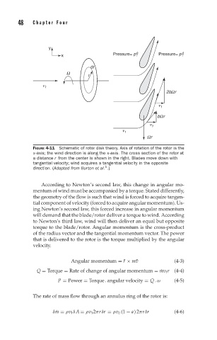
FIGURE 4-11 Schematic of rotor disk theory. Axis of rotation of the rotor is the
x-axis; the wind direction is along the x-axis. The cross section of the rotor at
a distance r from the center is shown in the right. Blades move down with
tangential velocity; wind acquires a tangential velocity in the opposite
1
direction. (Adapted from Burton et al. .)
According to Newton’s second law, this change in angular mo-
mentum of wind must be accompanied by a torque. Stated differently,
the geometry of the flow is such that wind is forced to acquire tangen-
tial component of velocity (forced to acquire angular momentum). Us-
ing Newton’s second law, this forced increase in angular momentum
will demand that the blade/rotor deliver a torque to wind. According
to Newton’s third law, wind will then deliver an equal but opposite
torque to the blade/rotor. Angular momentum is the cross-product
of the radius vector and the tangential momentum vector. The power
that is delivered to the rotor is the torque multiplied by the angular
velocity.
r
Angular momentum = ¯ × m¯v (4-3)
Q = Torque = Rate of change of angular momentum = ˙mv t r (4-4)
P = Power = Torque . angular velocity = Q .ω (4-5)
The rate of mass flow through an annulus ring of the rotor is:
δ ˙m = ρv 1 δA = ρv 1 2πrδr = ρv 0 (1 − a) 2πrδr (4-6)