
Page 67 - Fluid Power Engineering
P. 67
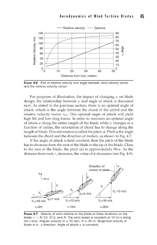
Aerodynamics of W ind T urbine Blades     45


                                  Relative velocity  Gamma
                     140                                     90
                                                             80
                    Relative Velocity, m/s  100              60   γ, degs
                     120
                                                             70
                      80
                                                             50
                                                             40
                      60
                                                             30
                      40
                      20
                                                             10
                       0                                     20
                                                             0
                        0      10     20     30     40     50
                                 Distance from hub, meters
              FIGURE 4-6 Plot of relative velocity and angle between wind velocity vector
              and the relative velocity vector.
                 For purposes of illustration, the impact of changing γ on blade
              design, the relationship between γ and angle of attack is discussed
              next. As stated in the previous section, there is an optimal angle of
              attack, which is the angle between the chord of the airfoil and the
              relative velocity vector v rel . This optimal angle of attack will yield
              high lift and low drag forces. In order to maintain an optimal angle
              of attack α along the entire length of the blade while γ changes as a
              function of radius, the orientation of chord has to change along the
              length of blade. This orientation is called the pitch, φ. Pitch is the angle
              between the chord and the direction of motion, as shown in Fig. 4-7.
                 If the angle of attack is held constant, then the pitch of the blade
              has to decrease from the root of the blade to the tip of the blade. Close
              to the root of the blade, the pitch (φ) is approximately 90-α.Asthe
              distance from root, r, increases, the value of φ decreases (see Fig. 4-9).


                                                Direction of  φ
                                                motion of blade  α
                     y
                                               φ
                          x                      α
                              φ
                                                      V r
                                 α    V r                   V t =10 m/s
                  γ  V r              γ    V t =5 m/s  γ
                          V t =1 m/s
                  V 1 =10 m/s      V 1 =10 m/s      V 1 =10 m/s
                   r=3m             r=15m            r=30m

              FIGURE 4-7 Velocity of wind relative to the blade at three locations on the
              blade, r = R/10, R/2, and R. The wind speed is constant at 10 m/s along
              the x-axis. Angular velocity
 = 20 rpm, R = 30 m. Tangential velocity of
              blade is in –y direction. Angle of attack α is constant.