
Page 66 - Fluid Power Engineering
P. 66
44 Chapter Four
Relative Velocity of Wind
The flow of air over an airfoil in the case of airplane is different com-
pared to a wind turbine. In the former, the angle of attack of wind is
constant along most of the length of the wing of an aircraft; in some
aircraft, the end of wing turns up, where the angle of attack changes. In
the case of wind turbines, the angle of attack changes along the length
of a blade. The angle of attack is with respect to the blade, meaning, it
is the angle at which wind strikes a blade as seen by an observer on the
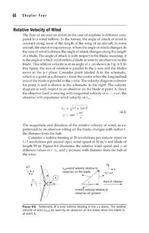
blade. This relative velocity is at an angle of γ , as shown in Fig. 4-5. In
this figure, the axis of rotation is parallel to the x-axis and the blades
move in the y-z plane. Consider point labeled A in the schematic,
which is a point at a distance r from the center when the longitudinal
axis of the blade is parallel to the z-axis. The velocity diagram is drawn
for point A and is shown in the schematic to the right. The velocity
diagram is with respect to an observer on the blade at point A. Since
the observer itself is moving with tangential velocity of v t =+ωr, the
observer will experience wind velocity of v rel .
2
v rel = v + (ωr) 2
ωr (4-1)
−1
γ = tan
v
The magnitude and direction of the relative velocity of wind, as ex-
perienced by an observer sitting on the blade, changes with radius r,
the distance from the hub.
Consider a turbine turning at 20 revolutions per minute (rpm) or
1/3 revolutions per second (rps), wind speed of 10 m/s and blade of
length 50 m. Figure 4-6 illustrates the relative wind speed and γ at
different values of r . v rel and γ increase with distance from the hub of
the rotor.
y
y
v rel =wind velocity relative to x
x observer on the blade
z v t =−ωr
r
ω A
γ Axis of rotation
v=wind velocity relative to
observer on ground
FIGURE 4-5 Schematic of a wind turbine rotating in the y-z plane. The relative
velocity of wind (v rel ) as seen by an observer on the blade when the blade is
at point A.