
Page 68 - Fluid Power Engineering
P. 68
46 Chapter Four
FIGURE 4-8 Relation-
ship between angle
of attack, pitch
angle, and angle α
between relative φ
velocity and
tangential velocity. V r V t
γ β
V 1
This is the reason why blades of most large turbines have a twist. Close
to the hub, the blade airfoil chord is almost perpendicular to the plane
of rotation. At the farthest point from the hub, which is the tip of the
blade, the chord is at a small angle to the plane of rotation. Figure 4-7
shows the cross-section of blade at three different distances from the
hub. The blades are moving in the negative y direction.
Figure 4-8 explains the angles in more detail. The angle of attack
(α) plus the pitch angle (φ) is equal to the angle of relative velocity
with the direction of motion of the blade (β).
90 − γ = β = α + φ (4-2)
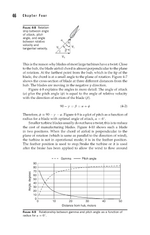
Therefore, φ = 90 − γ − α. Figure 4-9 is a plot of pitch as a function of
◦
radius for a blade with optimal angle of attack, α = 6 .
Smaller turbine blades usually do not have a twist; this is to reduce
the cost of manufacturing blades. Figure 4-10 shows such a blade
in two positions. When the chord of airfoil is perpendicular to the
plane of rotation (which is same as parallel to the direction of wind),
the turbine is not in operational mode; it is in the feather position.
The feather position is used to stop/brake the turbine or it is used
after the brake has been applied to allow the wind to flow around
Gamma Pitch angle
90
80
70
Angle, degrees 50
60
40
30
20
10
0
0 10 20 30 40 50
Distance from hub, meters
FIGURE 4-9 Relationship between gamma and pitch angle as a function of
◦
radius for α = 6 .