
Page 69 - Fluid Power Engineering
P. 69
Aerodynamics of W ind T urbine Blades 47
y
x
z
r
ω A
ωr
ωr
Position A: Feathered Position B: Operating
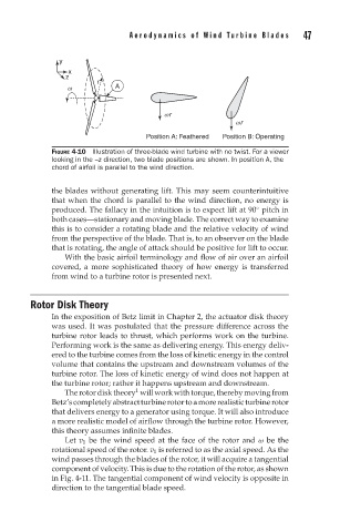
FIGURE 4-10 Illustration of three-blade wind turbine with no twist. For a viewer
looking in the –z direction, two blade positions are shown. In position A, the
chord of airfoil is parallel to the wind direction.
the blades without generating lift. This may seem counterintuitive
that when the chord is parallel to the wind direction, no energy is
produced. The fallacy in the intuition is to expect lift at 90 pitch in
◦
both cases—stationary and moving blade. The correct way to examine
this is to consider a rotating blade and the relative velocity of wind
from the perspective of the blade. That is, to an observer on the blade
that is rotating, the angle of attack should be positive for lift to occur.
With the basic airfoil terminology and flow of air over an airfoil
covered, a more sophisticated theory of how energy is transferred
from wind to a turbine rotor is presented next.
Rotor Disk Theory
In the exposition of Betz limit in Chapter 2, the actuator disk theory
was used. It was postulated that the pressure difference across the
turbine rotor leads to thrust, which performs work on the turbine.
Performing work is the same as delivering energy. This energy deliv-
ered to the turbine comes from the loss of kinetic energy in the control
volume that contains the upstream and downstream volumes of the
turbine rotor. The loss of kinetic energy of wind does not happen at
the turbine rotor; rather it happens upstream and downstream.
1
Therotordisktheory willworkwithtorque,therebymovingfrom
Betz’scompletelyabstractturbinerotortoamorerealisticturbinerotor
that delivers energy to a generator using torque. It will also introduce
a more realistic model of airflow through the turbine rotor. However,
this theory assumes infinite blades.
Let v 1 be the wind speed at the face of the rotor and ω be the
rotational speed of the rotor. v 1 is referred to as the axial speed. As the
wind passes through the blades of the rotor, it will acquire a tangential
component of velocity. This is due to the rotation of the rotor, as shown
in Fig. 4-11. The tangential component of wind velocity is opposite in
direction to the tangential blade speed.