
Page 76 - Fluid Power Engineering
P. 76
54 Chapter Four
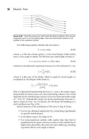
FIGURE 4-15 Fluid flow around an airfoil with the Kutta condition. The second
stagnation point is at the trailing edge. Note the downstream airflow is not
parallel to the upstream airflow.
The following equation defines the circulation:
= πv o c sin α (4-23)
where v o is the free stream speed, c is the chord length of the airfoil,
and α is the angle of attack. The lift force per unit length of blade is:
2
L = ρv 0 (πv o c sin α) = ρv πc sin α (4-24)
0
Lift force is traditionally expressed in terms of a lift coefficient (C L ) as:
1 2
L = ρSv C L (4-25)
0
2
where S is the area of the blade, which is equal to chord length (c)
multiplied by the length of the blade (l).
2
ρv πcl sin α
0
C L = = 2π sin α
1 2
2 ρSv 0
This is a theoretical relationship between C L and α, the attack angle.
Empirically, for small values of α, the relationship is linear. How small
depends on the airfoil design; typical values for alpha are in the range
◦
of −15 to 15 . Outside this range, the linear relationship between C L
and α ceases to exist. As α increases, the lift drops off resulting in a
stall condition (see Fig. 4-16).
Salient features of the coefficient of lift curve in Fig. 4-16 are:
Curves are obtained empirically by conducting experiments
on specific airfoil shapes
In the linear region, the slope is 2π
For nonsymmetrical airfoils with camber line (line that is
equidistant from upper and lower surface of the airfoil) that is
higher than chord line, the entire lift curve shifts up, resulting
in positive lift for zero angle of attack