
Page 166 - Wind Energy Handbook
P. 166
140 AERODYNAMICS OF HORIZONTAL-AXIS WIND TURBINES
r/R=30% 55% 75%
-4
30.41 18.12 + 12.94
+ +
-3 +
+ +
+ +
-2 +
+
+
-1 + +
+ + + + + + + + + + + + + + + + + + + + + + + +
+
+ + +
+ + + + + + + +
0 + + + + + +
+ + + + + + +
+ + + + + + +
1 + + +
Rotating Static
+
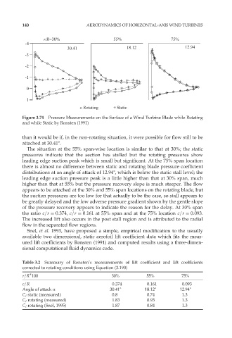
Figure 3.74 Pressure Measurements on the Surface of a Wind Turbine Blade while Rotating
and while Static by Ronsten (1991)
than it would be if, in the non-rotating situation, it were possible for flow still to be
attached at 30:418.
The situation at the 55% span-wise location is similar to that at 30%; the static
pressures indicate that the section has stalled but the rotating pressures show
leading edge suction peak which is small but significant. At the 75% span location
there is almost no difference between static and rotating blade pressure coefficient
distributions at an angle of attack of 12.948, which is below the static stall level; the
leading edge suction pressure peak is a little higher than that at 30% span, much
higher than that at 55% but the pressure recovery slope is much steeper. The flow
appears to be attached at the 30% and 55% span locations on the rotating blade, but
the suction pressures are too low for that actually to be the case, so stall appears to
be greatly delayed and the low adverse pressure gradient shown by the gentle slope
of the pressure recovery appears to indicate the reason for the delay. At 30% span
the ratio c=r ¼ 0:374, c=r ¼ 0:161 at 55% span and at the 75% location c=r ¼ 0:093.
The increased lift also occurs in the post stall region and is attributed to the radial
flow in the separated flow regions.
Snel, et al. 1993, have proposed a simple, empirical modification to the usually
available two dimensional, static aerofoil lift coefficient data which fits the meas-
ured lift coefficients by Ronsten (1991) and computed results using a three-dimen-
sional computational fluid dynamics code.
Table 3.2 Summary of Ronsten’s measurements of lift coefficient and lift coefficients
corrected to rotating conditions using Equation (3.190)
r=R 100 30% 55% 75%
c=R 0.374 0.161 0.093
Angle of attack Æ 30.418 18.128 12.948
C l static (measured) 0.8 0.74 1.3
C l rotating (measured) 1.83 0.93 1.3
C l rotating (Snel, 1995) 1.87 0.84 1.3