
Page 190 - Wind Energy Handbook
P. 190
164 AERODYNAMICS OF HORIZONTAL-AXIS WIND TURBINES
ΩR
4
ΩR
3
ΩR
2
ΩR
Ω
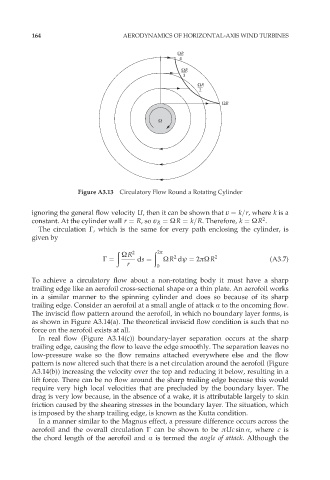
Figure A3.13 Circulatory Flow Round a Rotating Cylinder
ignoring the general flow velocity U, then it can be shown that v ¼ k=r, where k is a
2
constant. At the cylinder wall r ¼ R,so v R ¼ ÙR ¼ k=R. Therefore, k ¼ ÙR .
The circulation ˆ, which is the same for every path enclosing the cylinder, is
given by
ð 2 ð 2ð
ÙR
2
ˆ ¼ ds ¼ ÙR dł ¼ 2ðÙR 2 (A3:7)
r 0
To achieve a circulatory flow about a non-rotating body it must have a sharp
trailing edge like an aerofoil cross-sectional shape or a thin plate. An aerofoil works
in a similar manner to the spinning cylinder and does so because of its sharp
trailing edge. Consider an aerofoil at a small angle of attack Æ to the oncoming flow.
The inviscid flow pattern around the aerofoil, in which no boundary layer forms, is
as shown in Figure A3.14(a). The theoretical inviscid flow condition is such that no
force on the aerofoil exists at all.
In real flow (Figure A3.14(c)) boundary-layer separation occurs at the sharp
trailing edge, causing the flow to leave the edge smoothly. The separation leaves no
low-pressure wake so the flow remains attached everywhere else and the flow
pattern is now altered such that there is a net circulation around the aerofoil (Figure
A3.14(b)) increasing the velocity over the top and reducing it below, resulting in a
lift force. There can be no flow around the sharp trailing edge because this would
require very high local velocities that are precluded by the boundary layer. The
drag is very low because, in the absence of a wake, it is attributable largely to skin
friction caused by the shearing stresses in the boundary layer. The situation, which
is imposed by the sharp trailing edge, is known as the Kutta condition.
In a manner similar to the Magnus effect, a pressure difference occurs across the
aerofoil and the overall circulation ˆ can be shown to be ðUc sin Æ, where c is
the chord length of the aerofoil and Æ is termed the angle of attack. Although the