
Page 195 - Wind Energy Handbook
P. 195
VARIATION OF AEROFOIL CHARACTERISTICS WITH REYNOLDS NUMBER 169
60
NACA0012 Re=1 000 000
40
C l
C d Attached
flow region
20 Stalled region
0
0 5 10 15 20 25
α (degrees)
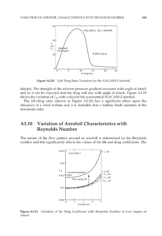
Figure A3.20 Lift/Drag Ratio Variation for the NACA0012 Aerofoil
sharply. The strength of the adverse pressure gradient increases with angle of attack
and so it can be expected that the drag will rise with angle of attack. Figure A3.19
shows the variation of C d with Æ also for the symmetrical NACA0012 aerofoil.
The lift/drag ratio (shown in Figure A3.20) has a significant affect upon the
efficiency of a wind turbine and it is desirable that a turbine blade operates at the
maximum ratio.
A3.10 Variation of Aerofoil Characteristics with
Reynolds Number
The nature of the flow pattern around an aerofoil is determined by the Reynolds
number and this significantly affects the values of the lift and drag coefficients. The
0.015 1 x 10 5
NACA0012
0.02
C d 5 x 10 5
Laminar boundary
0.015 layer 1 x 10 6
2 x 10 6
Decreasing Re
3 x 10 6
0.01
0.005
0 2 4 6 8
α (degrees)
Figure A3.21 Variation of the Drag Coefficient with Reynolds Number at Low Angles of
Attack