
Page 196 - Wind Energy Handbook
P. 196
170 AERODYNAMICS OF HORIZONTAL-AXIS WIND TURBINES
0.4
1.5
NACA0012 NACA0012 3 x 10 6
2 x 10 6
0.3 6
1 x 10
C d 1 Increasing Re 5 x 10 5 5
C l 1 x 10
0.2
1 x 10 5
5 x 10 5
1 x 10 6 0.5
0.1 2 x 10 6
Decreasing Re
3 x 10 6
0
0 5 10 15 20 25 0 5 10 15 20 25
α (degrees) α (degrees)
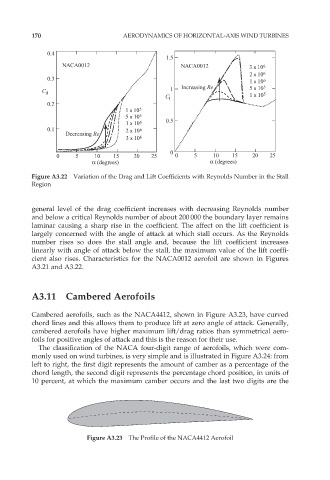
Figure A3.22 Variation of the Drag and Lift Coefficients with Reynolds Number in the Stall
Region
general level of the drag coefficient increases with decreasing Reynolds number
and below a critical Reynolds number of about 200 000 the boundary layer remains
laminar causing a sharp rise in the coefficient. The affect on the lift coefficient is
largely concerned with the angle of attack at which stall occurs. As the Reynolds
number rises so does the stall angle and, because the lift coefficient increases
linearly with angle of attack below the stall, the maximum value of the lift coeffi-
cient also rises. Characteristics for the NACA0012 aerofoil are shown in Figures
A3.21 and A3.22.
A3.11 Cambered Aerofoils
Cambered aerofoils, such as the NACA4412, shown in Figure A3.23, have curved
chord lines and this allows them to produce lift at zero angle of attack. Generally,
cambered aerofoils have higher maximum lift/drag ratios than symmetrical aero-
foils for positive angles of attack and this is the reason for their use.
The classification of the NACA four-digit range of aerofoils, which were com-
monly used on wind turbines, is very simple and is illustrated in Figure A3.24: from
left to right, the first digit represents the amount of camber as a percentage of the
chord length, the second digit represents the percentage chord position, in units of
10 percent, at which the maximum camber occurs and the last two digits are the
Figure A3.23 The Profile of the NACA4412 Aerofoil