
Page 194 - Wind Energy Handbook
P. 194
168 AERODYNAMICS OF HORIZONTAL-AXIS WIND TURBINES
where a 0 , called the lift-curve slope dC l =dÆ, is about 5.73 (0.1/degree), rather than
2ð. Note that a 0 should not be confused with the flow induction factor.
Lift, therefore, depends on two parameters, the angle of attack Æ and the flow
speed U. The same lift force can be generated by different combinations of Æ and U.
The variation of C l with the angle of attack Æ is shown in Figure A3.15 for a typical
symmetrical aerofoil (NACA0012). Notice that the simple relationship of Equation
(A3.6) is only valid for the pre-stall region, where the flow is attached, and because
the angle of attack is small (, 168) the equation is often written as
C l ¼ a 0 Æ (A3:10a)
A3.9 Aerofoil Drag Characteristics
The definition of the drag coefficient for an aircraft wing or a wind-turbine blade is
based not on the frontal area but on the plan area, for reasons that will become clear
later. The flow past a body which has a large span normal to the flow direction is
basically two-dimensional and in such cases the drag coefficient can be based upon
the drag force per unit span using the stream-wise chord length for the definition:
Drag=unit span
C d ¼ (3:11)
1 2
rU c
2
For a wing of large span the value of C d is roughly 0.01, at moderate Reynolds
numbers.
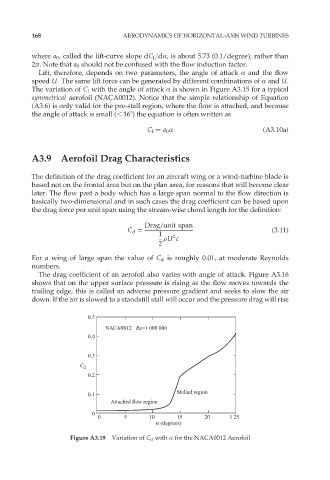
The drag coefficient of an aerofoil also varies with angle of attack. Figure A3.16
shows that on the upper surface pressure is rising as the flow moves towards the
trailing edge, this is called an adverse pressure gradient and seeks to slow the air
down. If the air is slowed to a standstill stall will occur and the pressure drag will rise
0.5
NACA0012 Re=1 000 000
0.4
0.3
C d
0.2
Stalled region
0.1
Attached flow region
0
0 5 10 15 20 1 25
α (degrees)
Figure A3.19 Variation of C d with Æ for the NACA0012 Aerofoil