
Page 197 - Wind Energy Handbook
P. 197
CAMBERED AEROFOILS 171
10 x B% chord
NACA AB12 Aerofoil
12% thickness/chord ratio
30% chord
Camber line
o
A
A% chord
Chord line
Zero lift line
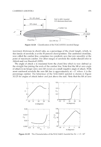
Figure A3.24 Classification of the NACAXXXX Aerofoil Range
maximum thickness to chord ratio, as a percentage of the chord length, which, in
this family of aerofoils, is at the 30 percent chord position. The cambered chordline,
now called the camber line, comprises two parabolic arcs that join smoothly at the
point of maximum camber. For other ranges of aerofoils the reader should refer to
Abbott and von Doenhoff (1959).
The angle of attack Æ is measured form the chord line which is now defined as
the straight line joining the ends of the camber line. Note that the lift at zero angle
of attack is no longer zero; zero lift occurs at a small negative angle of attack. With
most cambered aerofoils the zero lift line is approximately at A8 where A is the
percentage camber. The behaviour of the NACA4412 aerofoil is shown in Figure
A3.25 for angles of attack below and just above the stall. Note that the lift at zero
2 0.6
1 0.4
C l C d
0 0.2
-1 0
-10 0 10 20 30 -10 0 10 20 30
α (degrees) α (degrees)
0.02 150
100
0.015 C l
C d C 50
d
0.01
0
0.005 -50
-0.5 0 0.5 1 1.5 -10 -5 0 5 10
C l α (degrees)
Figure A3.25 The Characteristics of the NACA4412 Aerofoil for Re ¼ 1:5 10 6