
Page 220 - Wind Energy Handbook
P. 220
194 WIND-TURBINE PERFORMANCE
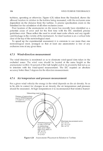
turbines, operating or otherwise. Figure 4.20, taken from the Standard, shows the
allowed location in relation to the turbine being measured, with the exclusion zone
dependent on the distance from the turbine. A precise specification exists in the
Standard for the calculation of all other exclusion zones.
Poor location of the anemometer on the tower has recently been identified as a
potential cause of error and for the first time with the IEC standard, precise
guidelines exist. These reflect the need to avoid mast wake effects and any signifi-
cant blockage in the vicinity of the instrument. An ideal location is on a vertical tube
clear of the top of the meteorological mast.
To speed up the experimental assessment it is common to use more than one
meteorological mast, arranged so that at least one anemometer is free of any
exclusion zone at any given time.
4.7.3 Wind-direction measurement
The wind direction is monitored so as to eliminate wind-speed data taken in the
excluded zones. The wind vane should be located at the same height as the
anemometer (within 10 percent of the hub height) and in its proximity but not so as
to interfere with the wind-speed measurement. The IEC requires an absolute
accuracy better than 5 degrees for the direction measurement.
4.7.4 Air temperature and pressure measurement
For a given wind velocity the energy in the wind depends on the air density. So as
to be able to correct for changes in air density, the air temperature and pressure
should be measured. At high temperatures it is recommended that relative humid-
Meteorology mast at 4 D
Distance of meteorology
mast to WTGS between
2 D and 4 D, 2,5 D is 2,5 D
recommended 2 D
Wind
D
WTGS
Maximum measurement sector:
Disturbed sector due 257 at 2 D
to wake of WTGS 267 at 2,5 D
on meteorology 286 at 4 D
mast; sector angle
taken from annex A:
103 at 2 D
93 at 2,5 D
74 at 4 D
Figure 4.20 Anemometer Placement in Relation to Turbine