
Page 242 - Wind Energy Handbook
P. 242
216 DESIGN LOADS FOR HORIZONTAL-AXIS WIND TURBINES
45
40
35
Hub-height wind speed (m/s) 25
30
20
15
Standard deviation of turbulent wind speed fluctuations = 3.9 m/s
10
Factor Beta = 6.4
Duration of gust = 14 s
5 Turbine diameter = 40 m, Turbulence scale parameter = 21m
0
-2 -1 0 1 2 3 4 5 6 7 8 9 10 11 12 13 14 15 16
Time (s)
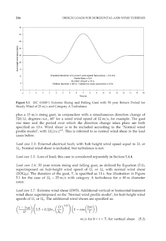
Figure 5.1 IEC 61400-1 Extreme Rising and Falling Gust with 50 year Return Period for
Steady Wind of 25 m=s and Category A Turbulence
plus a 15 m=s rising gust, in conjunction with a simultaneous direction change of
720=U r degrees—i.e., 608 for a rated wind speed of 12 m=s, for example. The gust
rise time and the period over which the direction change takes place are both
specified as 10 s. Wind shear is to be included according to the ‘Normal wind
0:2
profile model’, with U(z)1z . This is referred to as normal wind shear in the load
cases below.
Load case 1.4: External electrical fault, with hub height wind speed equal to U r or
U o . Normal wind shear is included, but turbulence is not.
Load case 1.5: Loss of load; this case is considered separately in Section 5.4.4.
Load case 1.6: 50 year return rising and falling gust, as defined by Equation (5.1),
superimposed on hub-height wind speed of U r or U o with normal wind shear
(EOG 50 ). The duration of the gust, T, is specified as 14 s. See illustration in Figure
5.1 for the case of U o ¼ 25 m=s with category A turbulence for a 40 m diameter
rotor.
Load case 1.7: Extreme wind shear (EWS). Additional vertical or horizontal transient
wind shear superimposed on the ‘Normal wind profile model’, for hub-height wind
speeds of U r or U o . The additional wind shears are specified as:
0:25 !
z z hub D 2ðt
2:5 þ 0:2âó u 1 cos
D ¸ 1 T
m=s for 0 , t , T, for vertical shear (5:2)