
Page 243 - Wind Energy Handbook
P. 243
EXTREME LOADS 217
!
0:25
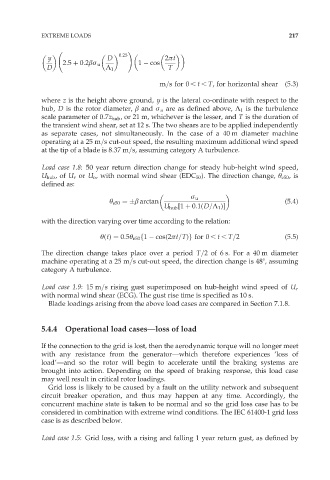
y D 2ðt
2:5 þ 0:2âó u 1 cos
D ¸ 1 T
m=s for 0 , t , T, for horizontal shear (5:3)
where z is the height above ground, y is the lateral co-ordinate with respect to the
hub, D is the rotor diameter, â and ó u are as defined above, ¸ 1 is the turbulence
scale parameter of 0:7z hub , or 21 m, whichever is the lesser, and T is the duration of
the transient wind shear, set at 12 s. The two shears are to be applied independently
as separate cases, not simultaneously. In the case of a 40 m diameter machine
operating at a 25 m=s cut-out speed, the resulting maximum additional wind speed
at the tip of a blade is 8:37 m=s, assuming category A turbulence.
Load case 1.8: 50 year return direction change for steady hub-height wind speed,
U hub ,of U r or U o , with normal wind shear (EDC 50 ). The direction change, Ł e50 ,is
defined as:
ó u
Ł e50 ¼ â arctan (5:4)
U hub [1 þ 0:1(D=¸ 1 )]
with the direction varying over time according to the relation:
Ł(t) ¼ 0:5Ł e50 f1 cos(2ðt=T)g for 0 , t , T=2 (5:5)
The direction change takes place over a period T=2 of 6 s. For a 40 m diameter
machine operating at a 25 m=s cut-out speed, the direction change is 488, assuming
category A turbulence.
Load case 1.9:15 m=s rising gust superimposed on hub-height wind speed of U r
with normal wind shear (ECG). The gust rise time is specified as 10 s.
Blade loadings arising from the above load cases are compared in Section 7.1.8.
5.4.4 Operational load cases—loss of load
If the connection to the grid is lost, then the aerodynamic torque will no longer meet
with any resistance from the generator—which therefore experiences ‘loss of
load’—and so the rotor will begin to accelerate until the braking systems are
brought into action. Depending on the speed of braking response, this load case
may well result in critical rotor loadings.
Grid loss is likely to be caused by a fault on the utility network and subsequent
circuit breaker operation, and thus may happen at any time. Accordingly, the
concurrent machine state is taken to be normal and so the grid loss case has to be
considered in combination with extreme wind conditions. The IEC 61400-1 grid loss
case is as described below.
Load case 1.5: Grid loss, with a rising and falling 1 year return gust, as defined by