
Page 284 - Wind Energy Handbook
P. 284
258 DESIGN LOADS FOR HORIZONTAL-AXIS WIND TURBINES
NACELLE
Blade tip -
deflected position
Q
Blade tip -
undeflected position
Blade section
with maximum twist
β
P
δ 11
δ 12
Weak principal axis
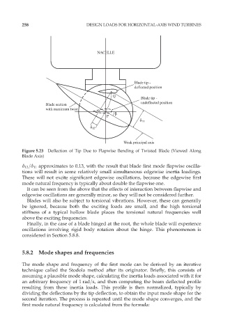
Figure 5.23 Deflection of Tip Due to Flapwise Bending of Twisted Blade (Viewed Along
Blade Axis)
ä 12 =ä 11 approximates to 0.13, with the result that blade first mode flapwise oscilla-
tions will result in some relatively small simultaneous edgewise inertia loadings.
These will not excite significant edgewise oscillations, because the edgewise first
mode natural frequency is typically about double the flapwise one.
It can be seen from the above that the effects of interaction between flapwise and
edgewise oscillations are generally minor, so they will not be considered further.
Blades will also be subject to torsional vibrations. However, these can generally
be ignored, because both the exciting loads are small, and the high torsional
stiffness of a typical hollow blade places the torsional natural frequencies well
above the exciting frequencies.
Finally, in the case of a blade hinged at the root, the whole blade will experience
oscillations involving rigid body rotation about the hinge. This phenomenon is
considered in Section 5.8.8.
5.8.2 Mode shapes and frequencies
The mode shape and frequency of the first mode can be derived by an iterative
technique called the Stodola method after its originator. Briefly, this consists of
assuming a plausible mode shape, calculating the inertia loads associated with it for
an arbitrary frequency of 1 rad=s, and then computing the beam deflected profile
resulting from these inertia loads. This profile is then normalized, typically by
dividing the deflections by the tip deflection, to obtain the input mode shape for the
second iteration. The process is repeated until the mode shape converges, and the
first mode natural frequency is calculated from the formula: