
Page 289 - Wind Energy Handbook
P. 289
BLADE DYNAMIC RESPONSE 263
of strain, i.e., as an additional moment which results in an additional lateral load.
Equation (5.62) can thus be written
2
2
@ 2 @ @ x @ 2 @ x
x
c
m(r)€ x þ ^ c a (r) _ x þ a 1 EI(r) þ EI(r) ¼ q(r, t) (5:79)
x
@r 2 @t @r 2 @r 2 @r 2
c
where ^ c a (r) is the aerodynamic damping per unit length, and a 1 is a constant
P
defining the magnitude of the structural damping. Inserting x(t, r) ¼ 1 f
j¼1 j (t)ì j (r)
as before, and using Equation (5.65), the structural damping term becomes
P
1 2 _
f
a
J¼1 1 m(r)ø ì j (r) f j (t). Thus the structural damping per unit length for the jth
j
2
mode is a 1 m(r)ø ì j (r), and therefore varies as the mass per unit length as assumed
j
in the Section 5.8.1. Continuing with the same procedure as in the Section 5.8.1, a
modified modal response equation is obtained as follows
ð
R
€
2 _
2
f
f
m i f i (t) þfc ai þ a 1 m i ø gf i (t) þ m i ø f i (t) ¼ ì i (r) p(r, t)dr (5:80)
i
i
0
Thus the structural damping ratio for the ith mode, defined as î si ¼
2
c si =2m i ø i ¼ a 1 m i ø =2m i ø i , becomes î si ¼ a 1 ø i =2, i.e., it increases in proportion to
i
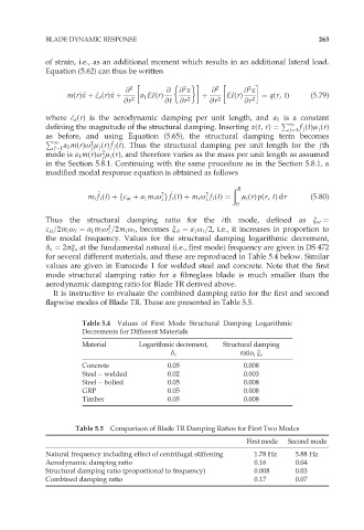
the modal frequency. Values for the structural damping logarithmic decrement,
ä s ¼ 2ðî s at the fundamental natural (i.e., first mode) frequency are given in DS 472
for several different materials, and these are reproduced in Table 5.4 below. Similar
values are given in Eurocode 1 for welded steel and concrete. Note that the first
mode structural damping ratio for a fibreglass blade is much smaller than the
aerodynamic damping ratio for Blade TR derived above.
It is instructive to evaluate the combined damping ratio for the first and second
flapwise modes of Blade TR. These are presented in Table 5.5.
Table 5.4 Values of First Mode Structural Damping Logarithmic
Decrements for Different Materials
Material Logarithmic decrement, Structural damping
ä s ratio, î s
Concrete 0.05 0.008
Steel – welded 0.02 0.003
Steel – bolted 0.05 0.008
GRP 0.05 0.008
Timber 0.05 0.008
Table 5.5 Comparison of Blade TR Damping Ratios for First Two Modes
First mode Second mode
Natural frequency including effect of centrifugal stiffening 1.78 Hz 5.88 Hz
Aerodynamic damping ratio 0.16 0.04
Structural damping ratio (proportional to frequency) 0.008 0.03
Combined damping ratio 0.17 0.07