
Page 293 - Wind Energy Handbook
P. 293
BLADE DYNAMIC RESPONSE 267
oscillations have largely died away after a complete revolution because of the
relatively high levels of damping.
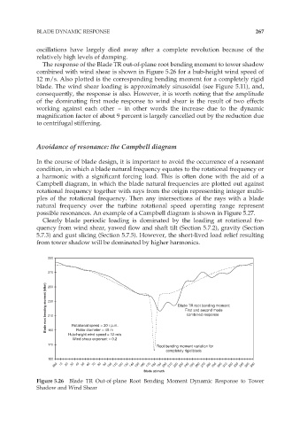
The response of the Blade TR out-of-plane root bending moment to tower shadow
combined with wind shear is shown in Figure 5.26 for a hub-height wind speed of
12 m/s. Also plotted is the corresponding bending moment for a completely rigid
blade. The wind shear loading is approximately sinusoidal (see Figure 5.11), and,
consequently, the response is also. However, it is worth noting that the amplitude
of the dominating first mode response to wind shear is the result of two effects
working against each other – in other words the increase due to the dynamic
magnification factor of about 9 percent is largely cancelled out by the reduction due
to centrifugal stiffening.
Avoidance of resonance: the Campbell diagram
In the course of blade design, it is important to avoid the occurrence of a resonant
condition, in which a blade natural frequency equates to the rotational frequency or
a harmonic with a significant forcing load. This is often done with the aid of a
Campbell diagram, in which the blade natural frequencies are plotted out against
rotational frequency together with rays from the origin representing integer multi-
ples of the rotational frequency. Then any intersections of the rays with a blade
natural frequency over the turbine rotational speed operating range represent
possible resonances. An example of a Campbell diagram is shown in Figure 5.27.
Clearly blade periodic loading is dominated by the loading at rotational fre-
quency from wind shear, yawed flow and shaft tilt (Section 5.7.2), gravity (Section
5.7.3) and gust slicing (Section 5.7.5). However, the short-lived load relief resulting
from tower shadow will be dominated by higher harmonics.
290
270
Blade root bending moment (kNm) 230 Blade TR root bending moment:
250
First and second mode
combined response
210
Rotational speed = 30 r.p.m.
Rotor diameter = 40 m
190
Hub-height wind speed = 12 m/s
Wind shear exponent = 0.2
170
Root bending moment variation for
completely rigid blade
150
360 10 20 30 40 50 60 70 80 90 100 110 120 130 140 150 160 170 180 190 200 210 220 230 240 250 260 270 280 290 300 310 320 330 340 350 360
Blade azimuth
Figure 5.26 Blade TR Out-of-plane Root Bending Moment Dynamic Response to Tower
Shadow and Wind Shear