
Page 298 - Wind Energy Handbook
P. 298
272 DESIGN LOADS FOR HORIZONTAL-AXIS WIND TURBINES
Teeter rotation
Blade A
Ω
δ 3
Axis of teeter hinge
Change in pitch angle
∆β = ζ tan δ 3
Teeter angle ζ
Centrifugal force
2
M(r)Ω r∆r
r
∆r
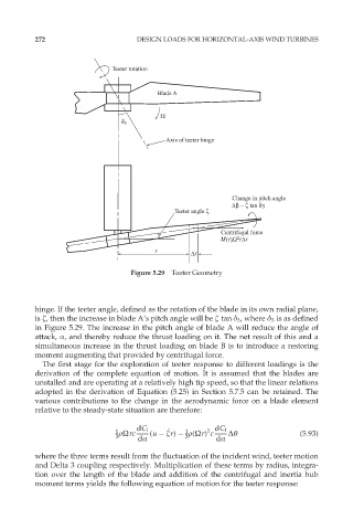
Figure 5.29 Teeter Geometry
hinge. If the teeter angle, defined as the rotation of the blade in its own radial plane,
is æ, then the increase in blade A’s pitch angle will be æ tan ä 3 , where ä 3 is as defined
in Figure 5.29. The increase in the pitch angle of blade A will reduce the angle of
attack, Æ, and thereby reduce the thrust loading on it. The net result of this and a
simultaneous increase in the thrust loading on blade B is to introduce a restoring
moment augmenting that provided by centrifugal force.
The first stage for the exploration of teeter response to different loadings is the
derivation of the complete equation of motion. It is assumed that the blades are
unstalled and are operating at a relatively high tip speed, so that the linear relations
adopted in the derivation of Equation (5.25) in Section 5.7.5 can be retained. The
various contributions to the change in the aerodynamic force on a blade element
relative to the steady-state situation are therefore:
1 dC l æ _ 1 2 dC l ˜Ł
2 rÙrc dÆ (u ær) r(Ùr) c dÆ (5:93)
2
where the three terms result from the fluctuation of the incident wind, teeter motion
and Delta 3 coupling respectively. Multiplication of these terms by radius, integra-
tion over the length of the blade and addition of the centrifugal and inertia hub
moment terms yields the following equation of motion for the teeter response: