
Page 301 - Wind Energy Handbook
P. 301
BLADE DYNAMIC RESPONSE 275
2.5
Diameter = 40 m
Rotational speed = 30 r.p.m. Power spectrum of
teeter angle x100
Mean wind speed = 12 m/s
2 Turbulence intensity = 8.33%
Integral length scale, L =73.5 m
Delta 3 angle = 0 degrees
Damping ratio = 0.444 Power spectrum of teeter angle x100
ignoring dynamic magnification (proportional
1.5 to spectrum of teeter moment)
nS(n)
Dynamic magnification ratio squared
1
0.5
0
0.01 0.1 1 10
Frequency (Hz)
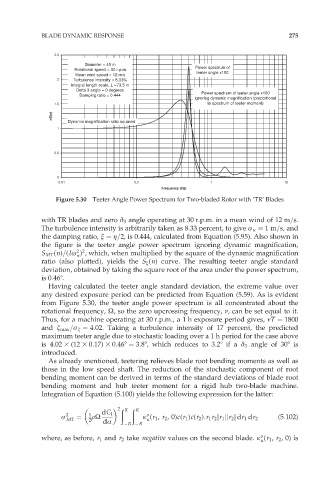
Figure 5.30 Teeter Angle Power Spectrum for Two-bladed Rotor with ‘TR’ Blades
with TR blades and zero ä 3 angle operating at 30 r.p.m. in a mean wind of 12 m=s.
The turbulence intensity is arbitrarily taken as 8.33 percent, to give ó u ¼ 1m=s, and
the damping ratio, î ¼ ç=2, is 0.444, calculated from Equation (5.95). Also shown in
the figure is the teeter angle power spectrum ignoring dynamic magnification,
2 2
S MT (n)=(Iø ) , which, when multiplied by the square of the dynamic magnification
n
ratio (also plotted), yields the S æ (n) curve. The resulting teeter angle standard
deviation, obtained by taking the square root of the area under the power spectrum,
is 0:468.
Having calculated the teeter angle standard deviation, the extreme value over
any desired exposure period can be predicted from Equation (5.59). As is evident
from Figure 5.30, the teeter angle power spectrum is all concentrated about the
rotational frequency, Ù, so the zero upcrossing frequency, í, can be set equal to it.
Thus, for a machine operating at 30 r.p.m., a 1 h exposure period gives, íT ¼ 1800
and æ max =ó æ ¼ 4:02. Taking a turbulence intensity of 17 percent, the predicted
maximum teeter angle due to stochastic loading over a 1 h period for the case above
is 4:02 3 (12 3 0:17) 3 0:468 ¼ 3:88, which reduces to 3:28 if a ä 3 angle of 308 is
introduced.
As already mentioned, teetering relieves blade root bending moments as well as
those in the low speed shaft. The reduction of the stochastic component of root
bending moment can be derived in terms of the standard deviations of blade root
bending moment and hub teeter moment for a rigid hub two-blade machine.
Integration of Equation (5.100) yields the following expression for the latter:
ð ð
2 R R
ó 2 ¼ 1 rÙ dC l o (5:102)
MT 2 dÆ R R k (r 1 , r 2 ,0)c(r 1 )c(r 2 ):r 1 r 2 jr 1 jjr 2 j dr 1 dr 2
u
o
where, as before, r 1 and r 2 take negative values on the second blade. k (r 1 , r 2 ,0) is
u