
Page 307 - Wind Energy Handbook
P. 307
BLADE DYNAMIC RESPONSE 281
20
Rotational speed = 30 r.p.m. = 3.142 rad/s = 0.5 Hz
Blade first mode frequency = 11.2 rad/s = 1.78 Hz out of plane
Tower first mode frequency = 7.3 rad/s = 1.16 Hz fore-aft
0
Deflection (mm) Tower top deflection x 10
Rotor: 3 No. ‘TR’ blades
-20 Rotor diameter = 40 m Blade damping ratio = 0.17
Wind speed = 12 m/s Tower damping ratio = 0.022
(uniform over disc)
Blade tip deflection
(dashed line applies to rigid tower)
-40
0 30 60 90 120 150 180 210 240 270 300 330 360
Blade azimuth (degrees)
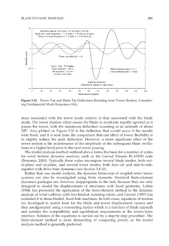
Figure 5.32 Tower Top and Blade Tip Deflections Resulting from Tower Shadow, Consider-
ing Fundamental Mode Responses Only
mass associated with the tower mode relative to that associated with the blade
mode. The tower shadow effect causes the blade to accelerate rapidly upwind as it
passes the tower, with the maximum deflection occurring at an azimuth of about
2058. Also plotted on Figure 5.32 is the deflection that would occur if the nacelle
were fixed, and it is seen from the comparison that one effect of tower flexibility is
to slightly reduce the peak deflection. However, a more significant effect of the
tower motion is the maintenance of the amplitude of the subsequent blade oscilla-
tions at a higher level prior to the next tower passing.
The modal analysis method outlined above forms the basis for a number of codes
for wind turbine dynamic analysis, such as the Garrad Hassan BLADED code
(Bossanyi, 2000). Typically these codes encompass several blade modes, both out-
of-plane and in-plane, and several tower modes, both fore–aft and side-to-side,
together with drive train dynamics (see Section 5.8.10).
Rather than use modal analysis, the dynamic behaviour of coupled rotor/tower
systems can also be investigated using finite elements. Standard finite-element
dynamics packages are, however, inappropriate to the task, because they are only
designed to model the displacements of structures with fixed geometry. Lobitz
(1984) has pioneered the application of the finite-element method to the dynamic
analysis of wind turbines with two-bladed, teetering rotors, and Garrad (1987) has
extended it to three-bladed, fixed-hub machines. In both cases, equations of motion
are developed in matrix form for the blade and tower displacement vectors and
then amalgamated using a connecting matrix which is a function of blade azimuth
and satisfies the compatibility and equilibrium requirements at the tower/rotor
interface. Solution of the equations is carried out by a step-by-step procedure. The
finite-element method is more demanding of computing power, so the modal
analysis method is generally preferred.