
Page 312 - Wind Energy Handbook
P. 312
286 DESIGN LOADS FOR HORIZONTAL-AXIS WIND TURBINES
2P,4P etc. Only the peaks at multiples of 3P remain, since at these frequencies the
three blades act in phase with each other.
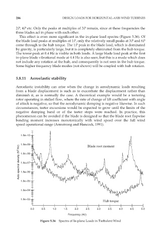
This effect is even more significant in the in-plane load spectra (Figure 5.36). Of
the blade load peaks at multiples of 1P, only the relatively small peaks at 3P and 6P
come through to the hub torque. The 1P peak in the blade load, which is dominated
by gravity, is particularly large, but it is completely eliminated from the hub torque.
The tower peak at 0.4 Hz is visible in both loads. A large blade load peak at the first
in-plane blade vibrational mode at 4.4 Hz is also seen, but this is a mode which does
not include any rotation at the hub, and consequently is not seen in the hub torque.
Some higher frequency blade modes (not shown) will be coupled with hub rotation.
5.8.11 Aeroelastic stability
Aeroelastic instability can arise when the change in aerodynamic loads resulting
from a blade displacement is such as to exacerbate the displacement rather than
diminish it, as is normally the case. A theoretical example would be a teetering
rotor operating in stalled flow, where the rate of change of lift coefficient with angle
of attack is negative, so that the aerodynamic damping is negative likewise. In such
circumstances, teeter excursions would be expected to grow until the limits of the
negative damping band or of the teeter stops were reached. In practice, this
phenomenon can be avoided if the blade is designed so that the blade root flapwise
bending moment increases monotonically with wind speed over the full wind
speed operational range (Armstrong and Hancock, 1991).
1.0e+10 Blade root moment
Auto spectral density (N 2 /Hz) 1.0e+09
1.0e+08
1.0e+07
1.0e+06
1.0e+05
1.0e+04
1.0e+03
Hub torque
0.0 0.5 1.0 1.5 2.0 2.5 3.0 3.5 4.0 4.5 5.0
Frequency (Hz)
Figure 5.36 Spectra of In-plane Loads in Turbulent Wind