
Page 329 - Wind Energy Handbook
P. 329
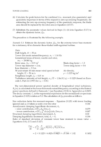
TOWER LOADING                                                          303


             (6) Calculate the peak factors for the combined (i.e., resonant plus quasistatic) and
                quasistatic responses in terms of the respective zero up-crossing frequencies. (In
                estimating the zero up-crossing frequency of the quasistatic response, the blade
                area should be replaced by the rotor area in Equation (A5.57).

             (7) Substitute the parameter values derived in Steps (1)–(6) into Equation (5.17) to
                obtain the dynamic factor, Q D .

             The procedure is illustrated by the following example.

             Example 5.3: Estimate the dynamic factor, Q D , for the extreme tower base moment
             for a stationary 40 m diameter three-bladed stall-regulated turbine.

               Data:
               Hub height, H ¼ 35 m
               Tower first mode natural frequency, n 1 ¼ 1:16 Hz
               Generalized mass of tower, nacelle and rotor,
                 m T1 ¼ 28 000 kg
               Rotor area, A R ¼ 23:9m 2                     Blade drag factor ¼ 1:3
               Tower top diameter ¼ 2m,                      Tower drag factor ¼ 0:6
               base diameter ¼ 3:5m
               50 year return 10 min mean wind speed at hub  Air density,
                 height, U ¼ 50 m=s                          r ¼ 1:225 kg=m 3
               Roughness length, z 0 ¼ 0:01 m
               Turbulence intensity at hub height, ó u =U ¼ 1=ln(H=z 0 ) ¼ 0:1225 (based on Euro-
               code 1, Part 2.4 (1997) for z 0 ¼ 0:01)

               The non-dimensional power spectral density of longitudinal wind turbulence,
             R u (n), is calculated at the tower first mode natural frequency according to the Kaimal
             power spectrum defined in Eurocode 1 (see Equation (A5.8) in Appendix) as 0.0425.
             The decay constant, C, in the exponential expression for the normalized co-spectrum
             in Equation (5.125) is taken as 9.2. The calculation of Q D procedes as follows.

             Size reduction factor for resonant response – Equation (5.125) with tower loading
             ignored and ì 1 (r) taken as unity over the rotor                    0.166
             Aerodynamic damping logarithmic decrement, ä a
               – rotor contribution, ó UC d A R =2m T1 n 1                        0.079
                                        Ð
                                         H
                                               2
                                               1
               – tower contribution, ó UC d 0  d(z)ì (z)dz=2m T1 n 1              0.007
             Structural damping logarithmic decrement, ä s                        0.02
             Damping logarithmic decrement, total, ä a þ ä s                      0.106
             Ratio of standard deviation of resonant tower base moment to mean value –
             Equations (5.6), (5.7) and (5.127)
                                        ð  p ffiffiffiffiffiffiffiffiffiffiffiffiffiffi p ffiffiffiffiffiffiffiffiffiffiffiffiffiffiffiffi
                            ó M1   ó u
                                ¼ 2   p ffiffiffiffiffiffi  R u (n 1 )  K Sx (n 1 )º M1
                             M      U   2ä
                                                  p ffiffiffiffiffiffiffiffiffiffiffiffiffiffi  p ffiffiffiffiffiffiffiffiffiffiffi
                                ¼ 2 3 0:1225 3 6:823 0:0425 3  0:166 3 1:02       0:1432