
Page 331 - Wind Energy Handbook
P. 331
TOWER LOADING 305
rotor thrust shows negligible azimuthal variation as a result of these effects. For
example, on two-bladed machines, a wind shear exponent of 0.2 results in a rotor
thrust variation of about þ/ 1 percent.
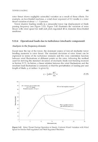
Tower shadow loading results in a sinusoidal tower top displacement at blade
passing frequency (see Figure 5.32). Figure 5.43 illustrates the variation of rotor
thrust with wind speed for stall and pitch regulated 40 m diameter three-bladed
machines.
5.12.4 Operational loads due to turbulence (stochastic component)
Analysis in the frequency domain
Except near the top of the tower, the dominant source of fore-aft stochastic tower
bending moments is rotor thrust. The standard deviation of rotor thrust can be
expressed in terms of the turbulence intensity and the cross correlation function
between wind fluctuations at different points on the rotor, following the method
used for deriving the standard deviation of stochastic blade root bending moment
in Section 5.7.5. As before, a linear relation between the wind fluctuations and the
resultant load fluctuations is assumed, so that the perturbation of loading per unit
length of blade, q, at radius r is given by
1
q ¼ rÙrc dC l u (5:25)
2 dÆ
100
90 40 m diameter three-bladed rotor
with ‘TR’ blades 500 kw Stall-regulated machine
Rotational speed = 30 r.p.m.
80
70
Rotor thrust (kN) 60
50
40
Pitch-regulated machine
with 400 kW power limit
30
20
10
0
0 5 10 15 20 25 30
Wind speed (m/s)
Figure 5.43 Rotor Thrust During Operation in Steady, Uniform Wind: Variation with Wind
Speed for Similar Stall-regulated and Pitch Regulated Machines