
Page 324 - Wind Energy Handbook
P. 324
298 DESIGN LOADS FOR HORIZONTAL-AXIS WIND TURBINES
5.11 Nacelle Loading
5.11.1 Loadings from rotor
The previous section considered the moments applied to the shaft by the rotor hub
using an axis system rotating with the shaft. In addition to these moments, the shaft
also experiences an axial load due to rotor thrust, and radial forces arising from
differential blade edgewise loadings and any out-of-balance centrifugal force.
In order to calculate loadings on the elements of the nacelle structure, it is first
necessary to transform the shaft loads (or the constituent blade loads) defined in
terms of the rotating axis system into nacelle loads expressed in terms of a fixed
axis system. Here the conventional system in which the x-axis is downwind, the y-
axis is horizontal to starboard and the z-axis is vertically upwards will be adopted
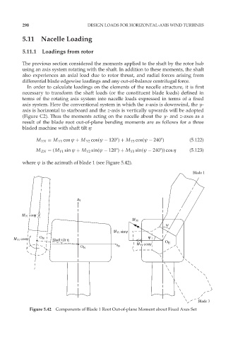
(Figure C2). Thus the moments acting on the nacelle about the y- and z-axes as a
result of the blade root out-of-plane bending moments are as follows for a three
bladed machine with shaft tilt ç:
M YN ¼ M Y1 cos ł þ M Y2 cos(ł 1208) þ M Y3 cos(ł 2408) (5:122)
M ZN ¼ (M Y1 sin ł þ M Y2 sin(ł 1208) þ M Y3 sin(ł 2408)) cos ç (5:123)
where ł is the azimuth of blade 1 (see Figure 5.42).
Blade 1
z N
M Y1 sinψ
M Y1
ψ
M Y1 sinψ
M Y1 cosψ O H Shaft tilt η ψ
M Y1 cosψ Ο Η
x N
O N
Blade 3
Figure 5.42 Components of Blade 1 Root Out-of-plane Moment about Fixed Axes Set