
Page 322 - Wind Energy Handbook
P. 322
296 DESIGN LOADS FOR HORIZONTAL-AXIS WIND TURBINES
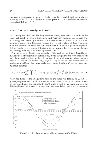
exponent are compared in Figure 5.41 for two- and three-bladed rigid hub machines
operating at 30 r.p.m. in a hub-height wind speed of 12 m=s. The ratio of moment
ranges is still close to 2:1:5.
5.10.3 Stochastic aerodynamic loads
The out-of-plane blade root bending moments arising from stochastic loads on the
rotor will result in both a fluctuating hub ‘dishing’ moment (see above) and
fluctuating shaft bending moments. For a two-bladed, rigid hub rotor, the shaft
moment is equal to the difference between the two out-of-plane blade root bending
moments, or teeter moment, the standard deviation of which is given by Equation
(5.102). Similarly, the standard deviation of the mean of these two moments (i.e.,
the ‘dishing’ moment) is given by Equation (5.103).
The derivation of the standard deviation of the shaft moment for a three-bladed
machine is at first sight more complicated, as the integration has to be carried out
over three blades instead of two. However, if the shaft moment about an axis
parallel to one of the blades, M ZS (Figure 5.35), is chosen, the contribution of
loading on that blade disappears, and the expression for the shaft moment standard
deviation becomes:
ð ð p ffiffiffi p ffiffiffi
2 R R 3 3
o
ó 2 ¼ 1 ˜Ù dC l k (r 1 , r 2 ,0)c(r 1 )c(r 2 ) (5:119)
Mzs 2 dÆ R R u 2 r 1 2 r 2 jr 1 jjr 2 j dr 1 dr 2
o
where the limits of the integrations refer to the other two blades. k (r 1 , r 2 ,0) is
u
given by Equation (5.51), with Ùô set equal to zero when r 1 and r 2 are radii to points
on the same blade, and replaced by 2ð=3when r 1 and r 2 are radii to points on
different blades. Note that, compared with the two-bladed case, the cross correla-
50
Shaft bending moment: two bladed rigid hub machine
40 Shaft bending moment: three bladed machine Rotational speed = 30 r.p.m.
Shaft bending moment about axis perpendicular to blade 1 -10 0 0 10 20 30 40 50 60 70 80 90 100 110 120 130 plane root bending moment 220 230 240 250 260 270 280 290 300 310 320 330 340 350 360
30
Rotor diameter = 40 m
Hub-height wind speed = 12 m/s
20
Shear exponent = 0.2
10
150
180
170
160
200
210
190
140
Blade 1 out-of-
-20
-30
-40
-50
Azimuth of blade 1 (degrees)
Figure 5.41 Shaft Bending Moment Fluctuation due to Wind Shear