
Page 383 - Wind Energy Handbook
P. 383
BRAKING SYSTEMS 357
900
800
700
0
600 -2
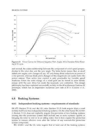
Power output (kW) 500 -3 500 kW
400
300 -4
-5
200
100
0
0 5 10 15 20 25 30 35
Wind speed (m/s)
Figure 6.12 Power Curves for Different Negative Pitch Angles: 40 m Diameter Rotor Rotat-
ing at 33 r.p.m.
and second, the cosine relationship between the component of wind speed perpen-
dicular to the rotor disc and the yaw angle. The latter factor means that, at small
initial yaw angles, yaw changes of, say, 108 only bring about reductions in power of
a few percent, whereas blade pitch changes of this magnitude can easily halve the
power output. Thus active yaw control is only practicable for variable speed
machines where the extra energy of a wind gust can be stored as rotor kinetic
energy until the yaw drive has made the necessary yaw correction. This design
philosophy has been exploited successfully in Italy on the 60 m diameter Gamma 60
prototype, which has an impressive maximum yaw rate of 88/s (Coiante et al.,
1989).
6.8 Braking Systems
6.8.1 Independent braking systems—requirements of standards
DS 472 (Section 5.1.4) and the GL rules (Section 5.1.3) both require that a wind
turbine shall have two independent braking systems. On the other hand, IEC 61400-
1 (Section 5.1.2) does not explicitly require the provision of two braking systems
(stating that the protection system shall include one or more systems capable of
bringing the rotor to rest or to an idling state), but it does require the protection
system to remain effective even after the failure of any non-safe-life protection
system component.
IEC 61400-1 and the GL rules require that at least one of the braking systems