
Page 379 - Wind Energy Handbook
P. 379
POWER CONTROL 353
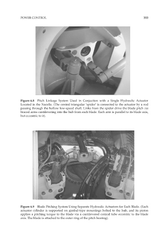
Figure 6.8 Pitch Linkage System Used in Conjuction with a Single Hydraulic Actuator
Located in the Nacelle. (The central triangular ‘spider’ is connected to the actuator by a rod
passing through the hollow low-speed shaft. Links from the spider drive the blade pitch via
braced arms cantilevering into the hub from each blade. Each arm is parallel to its blade axis,
but eccentric to it).
Figure 6.9 Blade Pitching System Using Separate Hydraulic Actuators for Each Blade. (Each
actuator cylinder is supported on gimbal-type mountings bolted to the hub, and its piston
applies a pitching torque to the blade via a cantilevered conical tube eccentric to the blade
axis. The blade is attached to the outer ring of the pitch bearing).