
Page 378 - Wind Energy Handbook
P. 378
352 CONCEPTUAL DESIGN OF HORIZONTAL-AXIS TURBINES
2000
15
12.5
1500
10
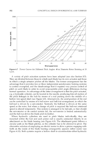
Power output (kW) 1000 7.5 5 2.5
500 0
500 kW
25
17.5
20 22.5
0
0 5 10 15 20 25 30
Wind speed (m/s)
Figure 6.7 Power Curves for Different Pitch Angles: 40 m Diameter Rotor Rotating at 33
r.p.m.
A variety of pitch actuation systems have been adopted (see also Section 8.5).
They are divided between those in which each blade has its own actuator and those
in which a single actuator pitches all the blades. The former arrangement has the
advantage that it provides two or three independent aerodynamic braking systems
to control overspeed, and the disadvantage that it requires very precise control of
pitch on each blade in order to avoid unacceptable pitch angle differences during
normal operation. An advantage of the latter arrangement is that the pitch actuator,
e.g. a hydraulic cylinder, can be located in the nacelle, producing fore-aft motion of
the pitch linkages in the hub by means of a rod passing down the middle of a
hollow low-speed shaft (see Figure 6.8). Alternatively, the axial position of the rod
can be controlled by means of a ball-screw and ball-nut arrangement, in which the
ball-nut is driven by a servomotor. Normally the ball-nut is driven at the same
speed as the rotor, but when a change of pitch is required the ball-nut rotational
speed is altered temporarily. This system is arranged to be fail-safe, so that should
the servomotor or its control system fail, the servomotor is braked automatically
and the ball-nut drives the blade pitch to feather.
Where hydraulic cylinders are used to pitch blades individually, they are
mounted within the hub and each piston rod is usually connected directly to an
attachment on the blade bearing (see Figure 6.9). The attachment point follows a
circular path as the blade pitches, so the cylinder has to be allowed to pivot. The
alternative solution of employing an electric motor to drive a pinion engaging with
teeth on the inside of the blade bearing consequently appears rather neater (see
Figure 6.10). Both systems require a hollow shaft to accommodate either hydraulic