
Page 69 - Wind Energy Handbook
P. 69
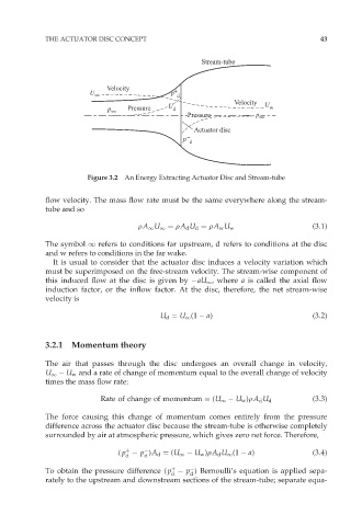
THE ACTUATOR DISC CONCEPT                                               43


                                                      Stream-tube


                             Velocity          +
                         U ∞                  p  d
                                                               Velocity  U
                             p ∞   Pressure  U d                        w
                                                  Pressure          p ∞

                                                    Actuator disc
                                                 p –
                                                   d


                        Figure 3.2  An Energy Extracting Actuator Disc and Stream-tube

             flow velocity. The mass flow rate must be the same everywhere along the stream-
             tube and so

                                     rA 1 U 1 ¼ rA d U d ¼ rA w U w                (3:1)

             The symbol 1 refers to conditions far upstream, d refers to conditions at the disc
             and w refers to conditions in the far wake.
               It is usual to consider that the actuator disc induces a velocity variation which
             must be superimposed on the free-stream velocity. The stream-wise component of
             this induced flow at the disc is given by  aU 1 , where a is called the axial flow
             induction factor, or the inflow factor. At the disc, therefore, the net stream-wise
             velocity is
                                           U d ¼ U 1 (1   a)                       (3:2)


             3.2.1  Momentum theory

             The air that passes through the disc undergoes an overall change in velocity,
             U 1   U w and a rate of change of momentum equal to the overall change of velocity
             times the mass flow rate:


                           Rate of change of momentum ¼ (U 1   U w )rA d U d       (3:3)
             The force causing this change of momentum comes entirely from the pressure
             difference across the actuator disc because the stream-tube is otherwise completely
             surrounded by air at atmospheric pressure, which gives zero net force. Therefore,

                                  þ

                                ( p   p )A d ¼ (U 1   U w )rA d U 1 (1   a)        (3:4)
                                  d    d
                                              þ

             To obtain the pressure difference ( p   p ) Bernoulli’s equation is applied sepa-
                                              d    d
             rately to the upstream and downstream sections of the stream-tube; separate equa-