
Page 72 - Wind Energy Handbook
P. 72
46 AERODYNAMICS OF HORIZONTAL-AXIS WIND TURBINES
1
C (a)
p
C (a)
T 0.5
0
0 0.2 0.4 0.6 0.8 1
a
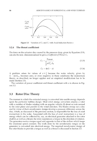
Figure 3.3 Variation of C P and C T with Axial Induction Factor a
3.2.4 The thrust coefficient
The force on the actuator disc caused by the pressure drop, given by Equation (3.9),
can also be non- dimensionalized to give a Coefficient of Thrust C T
Power
C T ¼ (3:15)
1 2
rU A d
1
2
C T ¼ 4a(1 a) (3:16)
A problem arises for values of a > 1 because the wake velocity, given by
2
(1 2a)U 1 , becomes zero, or even negative; in these conditions the momentum
theory, as described, no longer applies and an empirical modification has to be
made (Section 3.5).
The variation of power coefficient and thrust coefficient with a is shown in Fig-
ure 3.3.
3.3 Rotor Disc Theory
The manner in which the extracted energy is converted into usable energy depends
upon the particular turbine design. Most wind energy converters employ a rotor
with a number of blades rotating with an angular velocity Ù about an axis normal
to the rotor plane and parallel to the wind direction. The blades sweep out a disc
and by virtue of their aerodynamic design develop a pressure difference across the
disc, which, as discussed in the previous section, is responsible for the loss of axial
momentum in the wake. Associated with the loss of axial momentum is a loss of
energy which can be collected by, say, an electrical generator attached to the rotor
shaft if, as well as a thrust, the rotor experiences a torque in the direction of rotation.
The generator exerts a torque equal and opposite to that of the airflow which keeps
the rotational speed constant. The work done by the aerodynamic torque on the
generator is converted into electrical energy. The required aerodynamic design of
the rotor blades to provide a torque as well as a thrust is discussed in Section 3.5.