
Page 73 - Wind Energy Handbook
P. 73
ROTOR DISC THEORY 47
3.3.1 Wake rotation
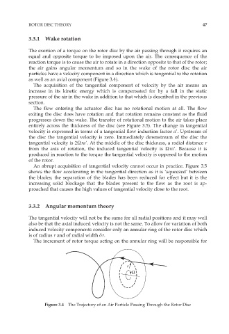
The exertion of a torque on the rotor disc by the air passing through it requires an
equal and opposite torque to be imposed upon the air. The consequence of the
reaction torque is to cause the air to rotate in a direction opposite to that of the rotor;
the air gains angular momentum and so in the wake of the rotor disc the air
particles have a velocity component in a direction which is tangential to the rotation
as well as an axial component (Figure 3.4).
The acquisition of the tangential component of velocity by the air means an
increase in its kinetic energy which is compensated for by a fall in the static
pressure of the air in the wake in addition to that which is described in the previous
section.
The flow entering the actuator disc has no rotational motion at all. The flow
exiting the disc does have rotation and that rotation remains constant as the fluid
progresses down the wake. The transfer of rotational motion to the air takes place
entirely across the thickness of the disc (see Figure 3.5). The change in tangential
velocity is expressed in terms of a tangential flow induction factor a9. Upstream of
the disc the tangential velocity is zero. Immediately downstream of the disc the
tangential velocity is 2Ùra9. At the middle of the disc thickness, a radial distance r
from the axis of rotation, the induced tangential velocity is Ùra9. Because it is
produced in reaction to the torque the tangential velocity is opposed to the motion
of the rotor.
An abrupt acquisition of tangential velocity cannot occur in practice. Figure 3.5
shows the flow accelerating in the tangential direction as it is ‘squeezed’ between
the blades; the separation of the blades has been reduced for effect but it is the
increasing solid blockage that the blades present to the flow as the root is ap-
proached that causes the high values of tangential velocity close to the root.
3.3.2 Angular momentum theory
The tangential velocity will not be the same for all radial positions and it may well
also be that the axial induced velocity is not the same. To allow for variation of both
induced velocity components consider only an annular ring of the rotor disc which
is of radius r and of radial width är.
The increment of rotor torque acting on the annular ring will be responsible for
r
Ω
Figure 3.4 The Trajectory of an Air Particle Passing Through the Rotor Disc