
Page 120 - Mechanical Behavior of Materials
P. 120
Section 4.1 Introduction 121
1920, and they are still frequently employed today. In the mechanical-screw-driven machine (top
diagram), rotation of two large threaded posts (screws) moves a crosshead that applies a force to the
specimen. A simple balance system is used to measure the magnitude of the force applied. Forces
may also be applied by using the pressure of oil pumped into a hydraulic piston (bottom diagram). In
this case, the oil pressure provides a simple means of measuring the force applied. Testing machines
of these types can be used for tension, compression, or bending, and torsion machines based on a
similar level of technology are also available.
The introduction of the Instron Corp. testing machine in 1946 represented a major step, in that
rather sophisticated electronics, based initially on vacuum tube technology, came into use. This is
also a screw-driven machine with a moving crosshead, but the electronics, used both in controlling
the machine and in measuring forces and displacements, makes the test system much more versatile
than its predecessors.
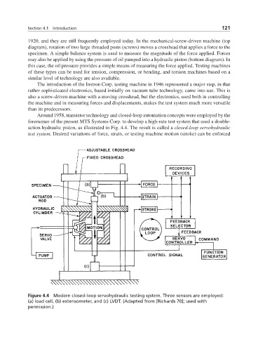
Around 1958, transistor technology and closed-loop automation concepts were employed by the
forerunner of the present MTS Systems Corp. to develop a high-rate test system that used a double-
action hydraulic piston, as illustrated in Fig. 4.4. The result is called a closed-loop servohydraulic
test system. Desired variations of force, strain, or testing machine motion (stroke) can be enforced
Figure 4.4 Modern closed-loop servohydraulic testing system. Three sensors are employed:
(a) load cell, (b) extensometer, and (c) LVDT. (Adapted from [Richards 70]; used with
permission.)