
Page 123 - Mechanical Behavior of Materials
P. 123
124 Chapter 4 Mechanical Testing: Tension Test and Other Basic Tests
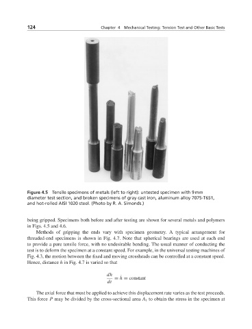
Figure 4.5 Tensile specimens of metals (left to right): untested specimen with 9 mm
diameter test section, and broken specimens of gray cast iron, aluminum alloy 7075-T651,
and hot-rolled AISI 1020 steel. (Photo by R. A. Simonds.)
being gripped. Specimens both before and after testing are shown for several metals and polymers
in Figs. 4.5 and 4.6.
Methods of gripping the ends vary with specimen geometry. A typical arrangement for
threaded-end specimens is shown in Fig. 4.7. Note that spherical bearings are used at each end
to provide a pure tensile force, with no undesirable bending. The usual manner of conducting the
test is to deform the specimen at a constant speed. For example, in the universal testing machines of
Fig. 4.3, the motion between the fixed and moving crossheads can be controlled at a constant speed.
Hence, distance h in Fig. 4.7 is varied so that
dh
= h = constant
˙
dt
The axial force that must be applied to achieve this displacement rate varies as the test proceeds.
This force P may be divided by the cross-sectional area A i to obtain the stress in the specimen at